
A boat wiring diagram with a fuse box splits one feeder into separate circuits, each with its own fuse. The feeder is protected by a main fuse within 7 inches of the battery under ABYC E-11 and 33 CFR 183.455. Each branch fuse is sized to its own wire. Every return goes back to a negative bus bar.
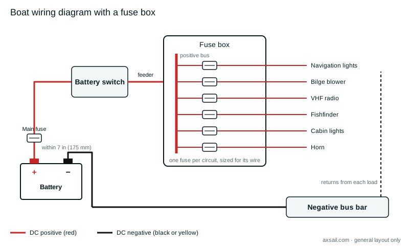
How the layout works
| Part | Job | Rule |
|---|---|---|
| Main fuse | Protects the feeder from the battery | Within 7 in (175 mm) of the battery, or 72 in (1.83 m) if the cable is sheathed all the way, under E-11 |
| Battery switch | Isolates the house circuits | In reach, as close as practicable to the battery |
| Feeder | Carries the total load to the fuse box | Sized for the total current and run length |
| Branch fuses | Protect each circuit's wire | No larger than the wire's allowable amperage, under 33 CFR 183.455 |
| Negative bus bar | Collects every return | Connected to the battery negative and the engine negative |
Sizing the fuses
A fuse protects the wire, so its rating follows the wire. 33 CFR 183.455 sets the maximum fuse rating from the conductor's allowable amperage in 183.425. The fuse size calculator does that lookup, and the wire size calculator picks the gauge for each circuit's current and length.
For surveyors
Open the fuse box and count the circuits against the labels. Look for fuses larger than their wire and for two circuits doubled up on one fuse. Loads taken straight off the battery post bypass the box altogether. Check the feeder has its main fuse at the battery end. With Axsail, say "fishfinder spliced into nav light circuit, no separate fuse" as you photograph the panel, and it's written up as a finding. The single battery diagram shows the rest of the system.