
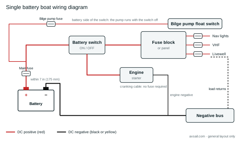
A single battery boat wiring diagram has four parts: a main fuse at the battery, a battery switch, a fuse block that splits the supply into circuits, and a negative bus that brings every return back to the battery. The layout below follows ABYC E-11 and 33 CFR 183.455, which both put the fuse within 7 inches of the battery. It's a general layout; a boat's own wiring diagram and the equipment makers' instructions come first.
The parts and the rules
| Part | What E-11 or 33 CFR 183 asks |
|---|---|
| Main fuse | Overcurrent protection within 7 in (175 mm) of the battery, measured along the conductor; up to 72 in (1.83 m) if the cable is in a sheath or enclosure all the way |
| Cranking cable | Exempt from the 7 inch rule |
| Battery switch | Required on a battery or bank over 800 CCA; mounted in reach, as close as practicable to the battery |
| Switch rating | Intermittent rating at least the largest cranking motor's maximum current |
| Battery side of the switch | Allowed for bilge pumps, blowers, alarms, CO detectors, memory for electronics and battery chargers |
| Fuse block | One fuse or breaker per circuit, sized to the wire it protects |
The bilge pump circuit
E-11 lets safety equipment bypass the battery switch, so an automatic bilge pump still runs when the boat is left with the switch off. In the diagram it's fed from the load side of the main fuse through its own fuse.
Sizing the wires and fuses
The wire size calculator gives the gauge for each run's current and length. The fuse size calculator gives the largest fuse 33 CFR 183 allows for that wire. Colours follow the boat wiring colour code.
For surveyors
Follow the positive cable from the battery: look for the main fuse and measure how far it sits from the terminal. Turn the switch off and lift the float switch to check the bilge pump still runs. Note any circuits taken straight off the battery post. With Axsail, say "no main fuse, battery positive runs unprotected 1.2 m to the switch" as you photograph it, and the finding is written against E-11.